
Introduction
Dimming is the process of regulating the power of an electrical device: controlling the power of different types of water or air heaters, light brightness, or the rotation speed of fans, pumps, and motors. In both domestic and industrial settings, dimmers are used everywhere: from simple lighting controls to industrial systems where heating elements (heating coils), motor speed control, and management of any high-power electrical installations are needed.
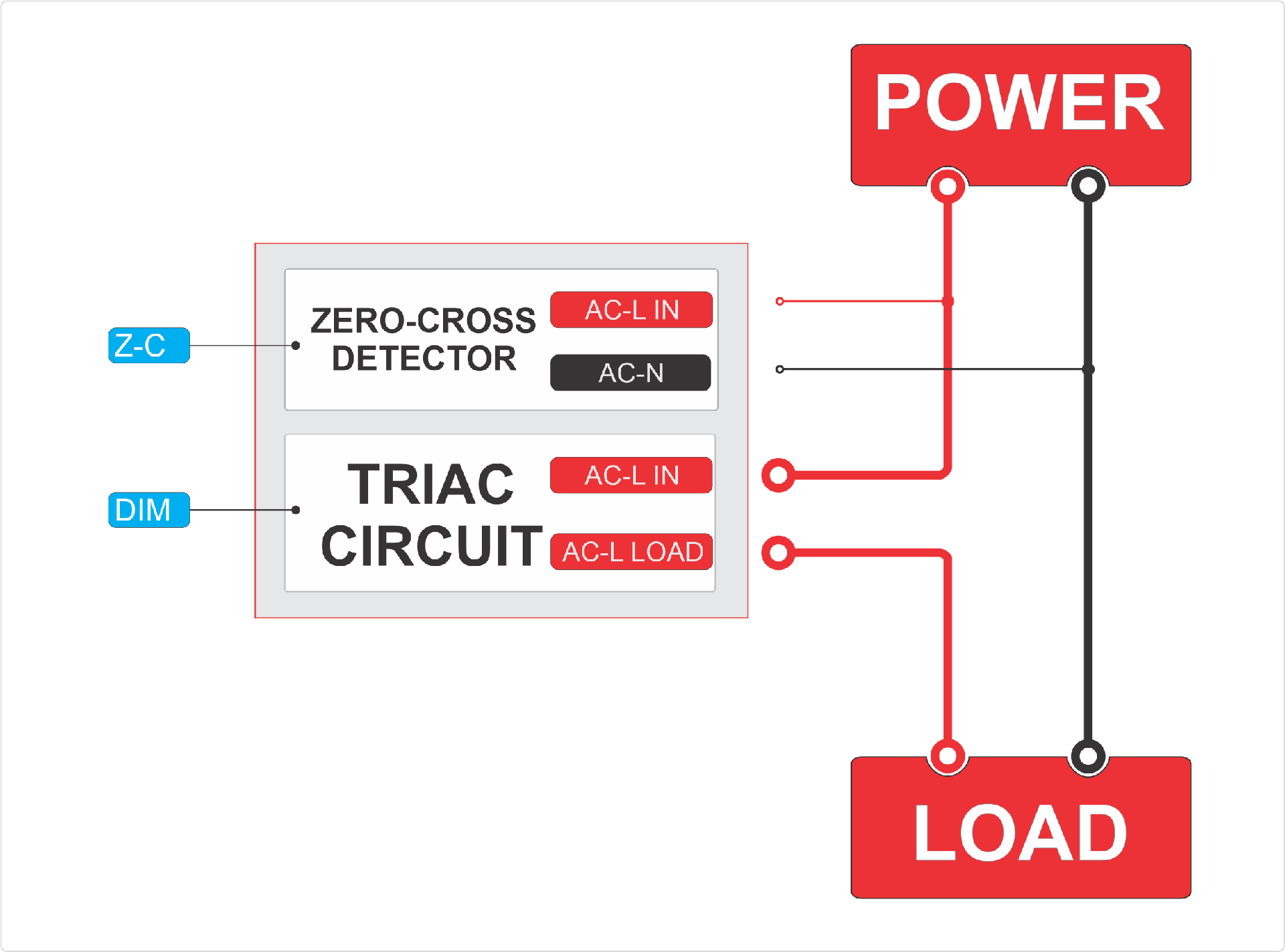
Modern AC dimmers (alternating current regulators) use semiconductor components for effective power control. The foundation of such a dimmer consists of two key elements:
- Zero-Cross detector
- Triac (Triode for Alternating Current)
Under microcontroller control, this circuit allows precise regulation of power supplied to the load, providing smooth changes in light brightness or motor rotation speed. This favorably distinguishes dimmers from simple contact relays or Solid State relays which have only 2 states: on and off.
Another important advantage of dimmers is their application for energy savings. Home electricity meters calculate consumed current for each half-wave (phase) of the AC sine wave. Therefore, a dimmer controlling current within the phase can fully control power consumption, unlike relays that cannot manage loads at such speed.
For example: If you have an economical tariff with a limit on household electricity consumption, or have solar panels with an inverter. Using a dimmer, you can avoid exceeding the limit by controlling the total electricity consumption. You can heat water in a boiler or warm up underfloor heating at 30-40%, and if someone turns on an electric kettle or TV in the house, the dimmer will immediately reduce the underfloor heating to ensure the total electricity consumption limit isn't exceeded. And as soon as the kettle is turned off, the dimmer will automatically increase floor heating while controlling the electricity consumption limit in the house. Your electric meter won't even notice the changes. Relays and switches cannot achieve this. This is truly a smart device.
Fundamentals of Alternating Current
Sinusoidal Nature of Alternating Current
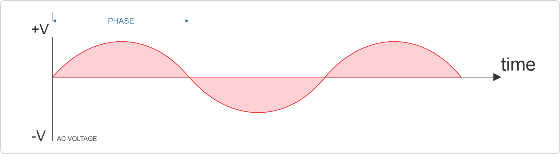
Alternating current (AC) in household electrical networks has a sinusoidal form. In Europe and most countries worldwide, the standard frequency of alternating current is 50 Hz, meaning 50 complete oscillations of the sine wave per second. In North America and some other countries, a frequency of 60 Hz is used.
The voltage in the network constantly changes from positive maximum to negative, passing through zero twice per period, or it can also be said 2 phases, one positive and followed by negative. A complete period of the sine wave is 20 milliseconds (10 ms per phase) at 50 Hz (or 16.7 ms at 60 Hz).
The Zero-Cross Concept
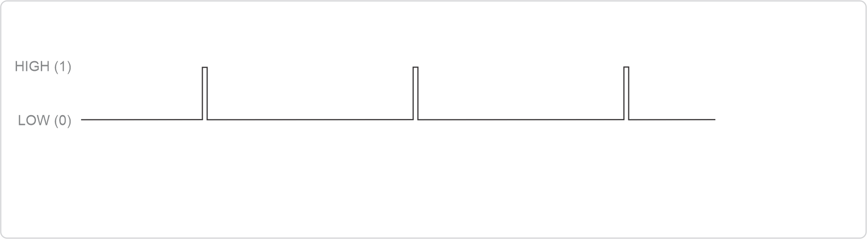
Zero-Cross is the moment when the AC voltage sine wave crosses the zero line, changing its sign. At this moment, the voltage is practically 0 Volts (not counting reactive currents in the network). This is a very short interval, and it can only be tracked by a microcontroller using a Zero-Cross detector. For a 50 Hz network, such transitions occur 100 times per second (twice per period).
Determining the zero-crossing moment is critical for dimmers because:
- At this moment, voltage and current are minimal
- Switching the load on or off at this point creates minimal electromagnetic interference
- It's convenient to start the delay timing for activation from this point
Active and Reactive Power
When working with alternating current, it's important to consider the difference between:
- Active power (converted into useful work — light, heat)
- Reactive power (circulates between the source and load, and is created by the devices themselves. Essentially these are parasitic currents that arise from components in electrical devices, such as capacitors and inductors)
The relationship between active and total power (active+reactive) is characterized by the power factor (cos φ), showing how efficiently energy is used. It's important for dimming: the closer cos φ is to 1, the better, the ideal ratio being total power = active power.
Operating Principle of the Dimmer
Phase Power Control
The principle of phase control is at the core of most modern dimmers. Its essence is that the dimmer controls and supplies electricity within the phase limits. The dimmer divides the phase into 2 parts, one part is off (cut off), in the 2nd part it's on. The larger portion of the period that is switched on, the more power is transferred to the load. And so the dimmer performs this process for each phase, i.e., 100 times per second for 50Hz.
We have of course shown the simplest power division. In practice, power depends on the sine wave angle, and its value is calculated using trigonometry. Fortunately, this is already implemented in libraries — you don't need to calculate manually. This is already accounted for in the dimmer control library, and you don't need to do calculations yourself.
It's important to note that the dimming module consists of 2 important components: a control optocoupler with optical isolation and a powerful TRIAC which switches current to the load. Also, the control optocoupler protects (galvanic isolation) the microcontroller from high currents from the AC network.
The control chip manages the TRIAC gate, closing the TRIAC at the zero-crossing moment, and opening the TRIAC on command from the microcontroller. It's sufficient to send a short pulse (20-50 microseconds) to the control optocoupler. After receiving the pulse, the control optocoupler keeps the TRIAC open until the current crosses zero (Zero-Cross).
The Role of TRIAC in Load Control
TRIAC (Triode for Alternating Current) is a semiconductor element (thyristor) capable of conducting current in both directions when a control signal is applied. Key features of TRIAC:
- Works in both half-waves (phases) of alternating current
- After opening, remains in a conductive state until the current through it falls below the threshold value (usually occurs when the sine wave crosses zero)
- Requires a relatively small control pulse to switch significant power
- Control optocoupler + TRIAC can be activated by a short pulse, no need to maintain the control signal throughout the entire conduction time
In the dimmer circuit, TRIAC plays the role of a high-speed electronic switch that connects the load to the network at specific times. Optocouplers are often used for control, providing galvanic isolation between the low-voltage control circuit (microcontroller) and the power part of the circuit.
Zero-Cross Detection and Its Significance
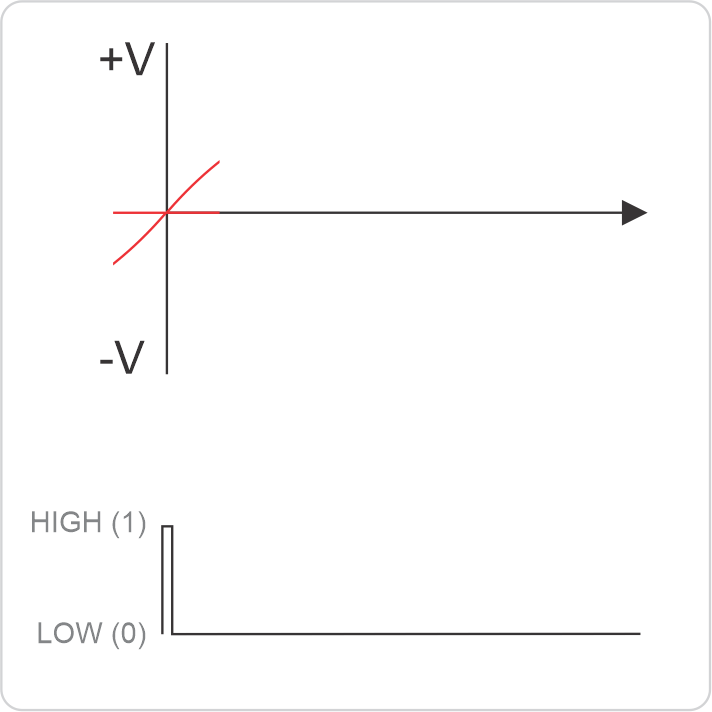
For proper operation of the dimmer, it is necessary to accurately determine the moments when the network voltage crosses zero (Zero-Cross). Special Zero-Cross detection circuits are used for this. In our dimmer: An optoisolator with a diode bridge. The diode bridge straightens the alternating current sine wave, and the optocoupler communicates the signal level to the microcontroller, high or low.
The zero-crossing signal is sent to the microcontroller, which is configured for hardware interrupt on input and uses it as a reference point for counting the TRIAC activation delay.
Types of Dimming
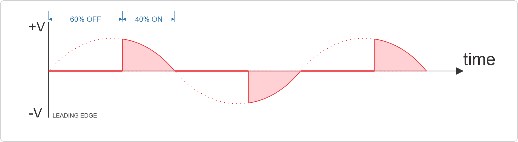
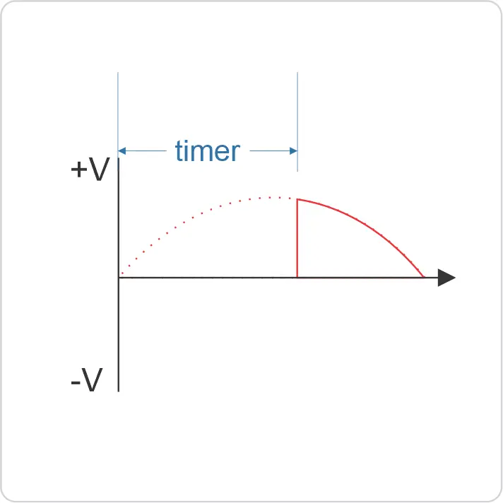
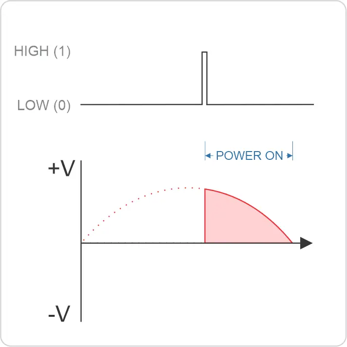
Leading Edge (L-dimming)
Leading Edge dimming is a method where the TRIAC is switched on after a calculated delay time following zero crossing, but remains on until the next zero crossing. Main features:
- TRIAC is switched on at a specific moment after zero crossing
- The longer the activation delay, the lower the average power to the load
- Sharp voltage rise during activation can create electromagnetic interference
This method is used in our dimmer. It is also common in household devices with dimming and is ideal for resistive loads.
Trailing Edge (T-dimming)
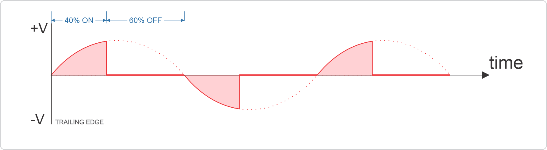
Trailing Edge dimming is a method where the switching module is turned on immediately after zero crossing, but is turned off at a specific moment before the next zero crossing. Features:
- Turns on directly at zero crossing
- Disconnection occurs at a calculated moment before the next zero crossing
- Provides smoother voltage rise, creates less interference
This method is more difficult to implement using TRIAC, as TRIAC does not turn off by control signal, but only when current falls below the holding value. For Trailing Edge implementation, more complex circuits with MOSFET or IGBT transistors are usually used.
Applicability to TRIAC Circuits
TRIAC dimmers by their nature are better suited for implementing Leading Edge dimming, as:
- After turning on, TRIAC remains open until the current crosses zero
- There is no direct way to turn off TRIAC before the natural zero crossing
Algorithm of Dimmer Operation with Microcontroller
Basic Dimmer Algorithm
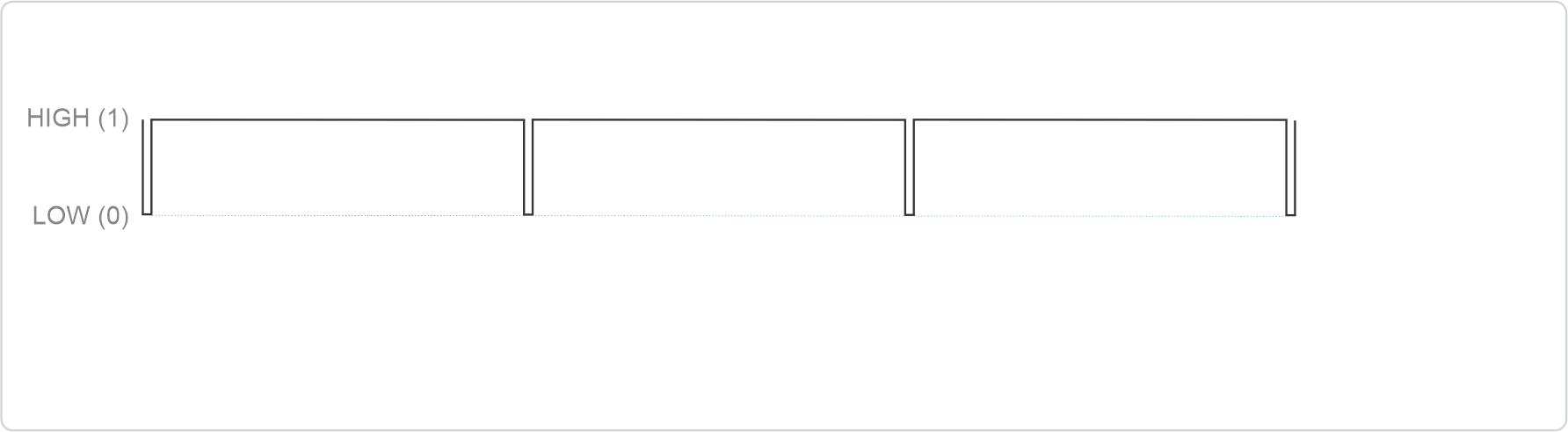
Zero-crossing detection
AC power crossing Zero point
Zero-Cross detector send the interrupt to microcontroller
The Dimmer control optocoupler closing the gate of TRIAC
Microcontroller Timer
Starting a timer to count the activation delay
Dimming impulse
After the specified delay time — sending a short pulse (usually 10-50 μs) to the TRIAC control electrode
TRIAC opens from the pulse and independently remains open until the next zero crossing
The process repeats for each phase (half-wave)
It's important to consider that the duration of the control pulse should be sufficient for reliable TRIAC opening, but it's not necessary to keep the control signal active throughout the entire TRIAC conduction. Otherwise, flickering effects may occur.
This feature allows efficient control of high-power loads using low-current signals from the microcontroller.
Delay Time Calculation
The TRIAC activation delay time directly determines the dimming level. For calculation, we apply a scale from 0 to 100%. For a 50 Hz network (period = phase 10 ms), the calculation can be done using the formula:
Delay (ms) = (100-dimming_level) / 100 × (period)
Where:
- dimming_level — current value (for example, from 0 to 100)
- period — phase length of the sine wave (10 ms)
For example, to set brightness at a level of 40 out of 100 (40%), the delay would be: (100-40) / 100 × (10ms) = 0.6 × 10 ms = 6 ms
After the Zero-Cross moment, wait 6 ms, open the TRIAC, TRIAC remains open for the remaining 4 ms. until the next Zero-Cross moment. And so in each half-period (phase).
Compatibility with Different Load Types
Ideal Loads for Dimming
Resistive Loads
- Incandescent lamps
- Heating elements
- Gas lamps (without electronic transformers, but it should be known that gas lamps have a minimum emission threshold in the gas, i.e., they won't glow below 30-100V)
These loads have a linear voltage-current characteristic and a power factor close to 1, making them ideal for dimming.
Specialized Dimmable Devices
- Dimmable LED drivers
- Dimmable transformers
- Special dimmable energy-saving lamps
These devices are designed with phase dimming characteristics in mind and have built-in electronics for correct signal interpretation.
Loads to Which RC Filters Should Be Applied
Inductive Loads
- Electric motors
- Fans
- Transformers
Inductive loads create a phase shift between current and voltage, which can lead to incorrect TRIAC operation, especially at low dimming levels. For this, the dimmer has an RC filter (snubber circuit) installed which smooths out starting currents. But it should be noted that electric motors may have built-in RC filters, which are designed for the motor winding inductance.
Non-Dimmable Electronic Loads
- Regular LED lamps
- Standard LED drivers
- Regular fluorescent lamps without dimming support
- Switching power supplies
- Electronic power stabilizers
- DC devices
These devices cannot be dimmed. They are designed for full voltage and have built-in power stabilization circuits.
Incompatibility Reasons
- Minimum TRIAC holding current — at low dimming levels, the current through some loads may be insufficient to keep the TRIAC in an open state
- Current waveform distortion — non-linear loads distort the shape of the consumed current, which can lead to unexpected TRIAC behavior
- Electromagnetic interference — sharp current changes when turning on TRIAC create interference that can affect sensitive electronics
- Capacitor charging period — switching power supplies have input capacitors that require initial charging current, which can disrupt dimmer operation
Practical Tips and Recommendations
Circuit Protection
- Use fuses of appropriate rating, both slow-blow and automatic circuit breakers
- Provide thermal protection for the TRIAC
Snubber Circuits for TRIAC Protection
A snubber circuit (usually consisting of a resistor and capacitor connected in series) performs several functions:
- Suppresses voltage spikes during switching
- Reduces the rate of voltage rise (dv/dt)
- Improves operation with inductive loads
The snubber circuit is already built into the dimmer.
Conclusion
Dimmers based on TRIAC and Zero-Cross detector represent an effective solution for controlling AC power. Despite their apparent simplicity, these devices require understanding the characteristics of alternating current and proper component selection to ensure reliable operation.
Modern microcontrollers significantly expand the capabilities of traditional dimmers, allowing implementation of complex control algorithms, remote control, and integration into "smart home" systems.
When developing or selecting a dimmer, it's important to consider the load type and requirements for smooth regulation, as well as take measures to reduce electromagnetic interference and ensure safe device operation.