
Your cart is currently empty!
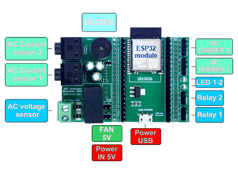
Step 1: Power Connection
To power the AC Power Smart Router, use one of the following options:
- Micro-USB Port – Connect a USB 5V power adapter (micro-USB only for power).
- DC 5V Pin Header – Use an external 5V DC power supply.
Ensure the power source provides at least 350mA for stable operation.
Step 2: AC Voltage Sensor
The AC Power Smart Router can measure the AC voltage of your home electrical network.
- Connect the electrical wire to the terminal.
- The trimmer resistor is pre-calibrated at the factory—no adjustments are needed.
⚠ Safety Notice: The AC voltage sensor includes an isolating transformer for safety. However, always ensure proper insulation and handling when working with AC voltage.
Step 3: Connecting Current Sensors
The current sensors connect to the jack inputs (AC Current sensor 1-2) on the AC Power Smart Router. You can connect up to two sensors—one for the grid or inverter, or load, depending on selected mode.
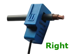
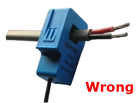
⚠ Important:
- When measuring current, make sure to pass only one wire through the sensor, as shown in the diagram below.
- If both wires (live and neutral) are placed inside the sensor, the readings will be canceled out, resulting incorrect values.
After connecting the sensors, configure them in the web application under Hardware Settings.
Step 4: Connecting Dimmers and Relays
Choosing the Right Dimmer for Your Heater
Before connecting, select a dimmer module with a power rating that matches your heating device. Use the interactive configurator at this link: [link] to determine the correct dimmer.
Wiring Diagram for Dimmers and Relays
The controller supports up to two dimmer modules (each with different power ratings) and two relay modules, allowing you to control different loads efficiently.
Pin Connections:
- Relays: GND, 5V, Signal
- Dimmers: VCC, GND, Zero-Cross, Dimming
Configuration in the Web Interface
After connecting, go to the Hardware Settings menu in the web interface to set the power rating of the connected dimmer or dimmable device.
For the correct wiring of your device to the dimmer, refer to the user manual included in the instructions [link] .
Step 5: Additional Equipment
If your project requires cooling, the controller have a DC 5V output for connecting a cooling fan.
Important Considerations:
- Ensure that your power supply can handle the additional load of the cooling fan.
- We recommend using cooling for dimmers to improve stabelity and longevity in your project.